


Calibration of Your Polar Desktop Laser Engraving Machine Camera: A Step-by-Step Guide
The OMTech Polar desktop laser engraving machine is one of the most sought-after CO2 laser devices in the current market, providing an ideal solution for small business owners in the laser engraving field, laser enthusiasts, as well as beginners in the art and craft sector looking to start with creative projects. A standout feature of the Polar is its 360-degree panoramic 5MP camera, allowing for image scanning and placement through a drag-and-drop function, enabling you to track the application of your designs on the material in real-time. The following will detail how to correctly calibrate the camera.
Preparation
Take note of the following items - a laptop, the camera cable, a double-sided USB cable, a wooden board measuring 510 x 300 mm, and a dot image with dimensions of 148 mm x 105 mm.
Connecting Cables
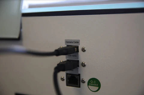
Thread the supplied camera cable from the back of the machine to the inside, open the buckle of the original camera cable, remove the cable, connect the supplied camera cable, and buckle it securely.
Connect the supplied double-sided USB cable to the machine and the computer respectively.
Connect the USB connector of the camera cable to the USB port of the notebook.
Place the prepared paper board, the wooden board, and the printed calibration file into the working area of the laser engraving machine.
Turn on the switch of the laser engraving machine.
Starting the Software
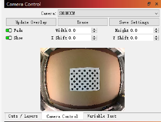
Open the LightBurn software on your computer and activate the "Camera Control" window. You will see a window as shown below:
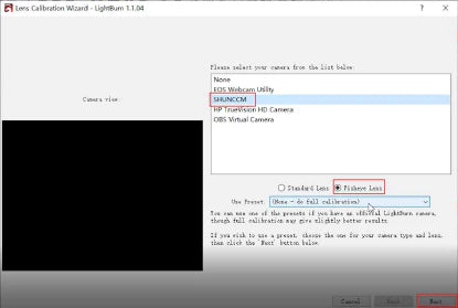
In the dropdown menu of "Laser Tools", click on "Calibrate Camera Lens", select "SHUNCCM" and "Fisheye Lens", and then click on "Next".
Close the activated Honeycomb check (Honeycomb check enabled).
Capture Calibration Pattern
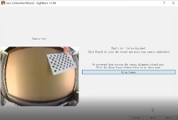
Click on the "Capture" button, as shown in the figure, place the "circular pattern" card in the camera view, and then click on "Capture". Try to achieve the lowest possible score - 0.3 or less is ideal. If the score is 1.0 or lower, click "Next" to proceed. (If you don't achieve it immediately, you can capture the current image again or go back to the beginning and try again. It may take several attempts to understand how to align the card with the camera to get the lowest score.)
During the capture, the images will update. The first five images are centered views, followed by views from below, the left side, the right side, and then the top. If the camera has a strong fisheye effect, it may be necessary to slightly move the non-centered images inwards to enable a successful capture. Once all steps are completed and you are satisfied with the good calibration results and undistorted images, click "Done" to save the result. You can also click on the "Align Camera" button on the last page to be automatically guided to the next wizard.
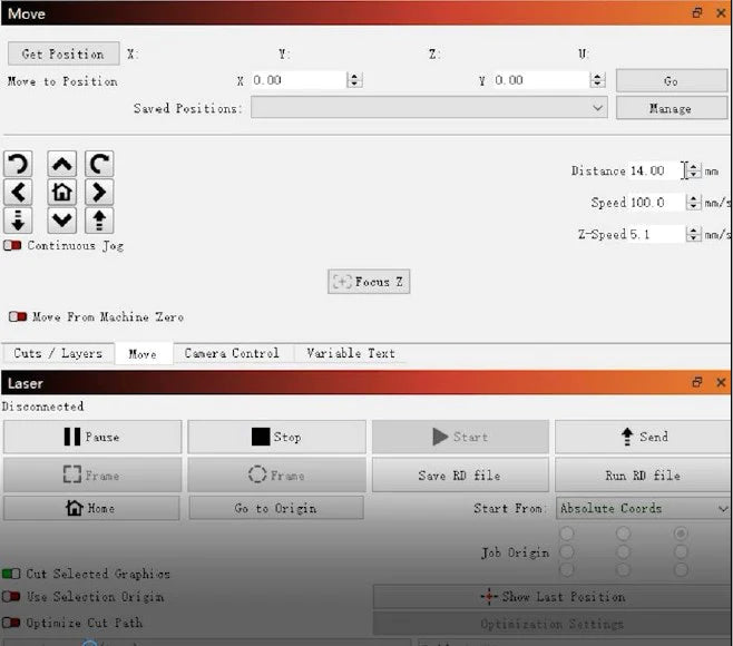
To adjust the focus - before proceeding to the next step - it is necessary to position the focus (Z-axis) correctly. Select "Move" from the menu and change the "Distance" to "14.00". Then click "↓" to lower the Z-axis.
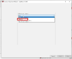
Open the "Laser Tools" menu and select the option "Calibrate Camera Alignment" to access the page for camera alignment calibration. Open the dropdown menu "select your camera" and choose SHUNCCM as your camera. Once the camera image appears on the page, click on Next.
Adjusting Parameters
Adjust the relevant parameters according to the on-screen prompts: Set material thickness to 3, fill speed to 100, fill power to 25%, line speed to 30, and line power also to 25%.
Check Engraving Area and Engrave
Click on "Frame" to check the machine's engraving area to ensure it aligns with the placed wooden board. Once you confirm the accuracy of the area, click the "Start" button to begin engraving. Wait for the machine to finish engraving, then click Next to proceed to the next page.
Capture Image
Click on the "Capture Image" button to display the camera image on the right side of the page. Confirm that it is correct, then click Next.
Set Calibration Points
Follow the instructions on the page to click on the centers of numbers 1, 2, 3, and 4 on the screen. Ensure that the ten-digit symbols generated overlap the crosshairs on the screen as accurately as possible. This process will ultimately form a standard square. Click Next to complete the camera alignment calibration.
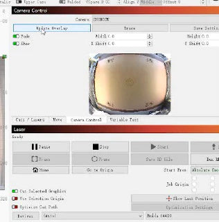
Select "Camera Control" from the menu to access the camera settings page. Click the "Update Overlay" button to upload the camera image to the editing page.
Perform Test Engraving and Verify Correction Success
Draw any shape on the editing page and process it to test the effectiveness of the correction by the cameras. If there is a deviation of 1-2mm between the shape on the editing page and the actual processed shape, it indicates that the correction was successful. If the deviation is too large, please repeat the correction steps.
Related Articles

